20.03.20; Mar.2020
Monitor 5
help

Area '840D'


Monitor5

Standard Settings (according to the connected NCU interface):


840D interfaces
X127: (Service Interface)
Address: 192.168.215.1
Rack: 0
Slot: 2


X120: (System Network)
Address: 192.168.214.1
Rack: 0
Slot: 2


X130: (Company Network)
Address: set by network administrator
Rack: 0
Slot: 2

Offline Functions:


Some functions of this program may be used offline.


Alarm Calculator:


1. Enter an Alarm number in the 'Alarm' field and press ENTER. Corresponding bit from DB2 is calculated in 'DB2 bit'.
   Examples: 510008, 700040, etc
2. Enter a bit number from DB2 in 'DB2 bit' field and press ENTER. Corresponding Alarm number is calculated in 'Alarm' field.
   Examples: DB2.DBX185.5 or DBX185.5 or 185.5


Note: When Connected, bit status (Alarm SET or Alarm NOT SET) is displayed and may be changed online with 'Set Bit' and 'Reset bit' buttons.


M Function Calculator:


Note: This function calculate only the 'Fast M decode' bits in Channel DB area from PLC. Only M0 to M99 are decoded, without extension. A full monitoring of M functions bits is available in '840D Func' Area.
For more information on decoding M function bits in PLC see the corresponding help.

1. Enter the Channel number in 'Chan' field and M function number in 'M fct.' field. Both DB number and bit number are calculated in 'bit' field.
   Examples: 'Chan:' 1 and 'M fct:' 3 or 'Chan:' 1 and 'M fct:' M3
2. Enter a bit number in 'bit' field and press ENTER. Corresponding M function number is calculated in 'M fct' field. If no DB number is entered, channel number is set to 0 (zero).
   Examples: DB22.DBX198.3 or DBX198.3 (no channel number will be calculated) or 198.3 (no channel number will be calculated)


Note: When Connected, bit status (M function SET or M function NOT SET) is displayed and may be changed online with 'Set Bit' and 'Reset bit' buttons.


Note: With 'Monitor' button the status change is monitored, retained and displayed even for 1-PLC-cycle changes.

To reset the status press 'Monitor' button once more.


Fast IO Calculator:

1. Enter an NCK Fast Input number in the 'Fast IO' field and press ENTER. Corresponding bits for 'PLC disable of the input', 'PLC set value' and 'Actual value from Hardware' from DB10 are calculated in the corresponding fields.

Note: When Connected, bit status is displayed.


Generic Variable:

This area is not functional.


Online Monitoring:


Online view
When online, some data regarding Axis status and Channel status are displayed.


Channel group:
Channel Number
User...
Use Up/Down Arrow from keyboard Select Channel number. Function disabled if 'Link Channel' is selected on Axis group.
Channel Status
NC -> PLC
DBch.DBX35.5 = Active
DBch.DBX35.6 = Interrupted
DBch.DBX35.7 = Reset


DBch = DB[20 + Channel Number]
Example: DB21 = Channel 1
Channel status:
Active: Channel is Active, a Part Program is running or an axis is moving;
Interrupted: Channel is Interrupted by:
        - DBch.DBX7.3 (NC Stop)
        - DBch.DBX7.4 (NC Stop axes plus spindles)
        - DBch.DBX7.2 (NC Stop at the block limit)
        - Programmed M00 or M01
        - Single-block mode
Reset: Channel is in Reset mode, no action is active;
Program Status
NC -> PLC
DBch.DBX35.0 = Running
DBch.DBX35.1 = Waiting
DBch.DBX35.2 = Stopped
DBch.DBX35.3 = Interrupted
DBch.DBX35.4 = Aborted


DBch = DB[20 + Channel Number]
Example: DB21 = Channel 1
Program status:
Running: DBX35.0: The part program was started with the interface signal DBch.DBX7.1 (NC Start) and is running.
Waiting: DBX35.1: The running program is waiting for the program command WAIT_M or WAIT_E in an NC block.
Stopped: DBX35.2: The NC part program has been stopped by:
        - DBch.DBX7.3 (NC Stop)
        - DBch.DBX7.4 (NC Stop axes plus spindles)
        - DBch.DBX7.2 (NC Stop at the block limit)
        - Programmed M00 or M01
        - Single-block mode
Interrupted: DBX35.3: When the operating mode changes from AUTOMATIC or MDI (in stopped program status) to JOG, the program status changes to "Interrupted".
Aborted: DBX35.4: No program is running in Channel; The program was not started, was finished with M2/M30/RET/etc or was aborted with a Reset.
Channel Ready
NC -> PLC
DBch.DBX36.5

DBch = DB[20 + Channel Number]
Example: DB21 = Channel 1
Channel is ready:
1 = OK: Channel is ready for part program processing of machine axes, geometry axes and positioning axes.
0 = NO: Channel is not ready for a part program processing of machine axes, geometry axes and positioning axes.
Channel NC Alarm
NC -> PLC
DBch.DBX36.6

DBch = DB[20 + Channel Number]
Example: DB21 = Channel 1
Channel-specific NCK alarm is active:
0 = NO: No NCK alarm is active for this channel.
1 = YES: At least one NCK alarm is present for this channel.
NC Alarm
NC -> PLC
DBch.DBX36.7

DBch = DB[20 + Channel Number]
Example: DB21 = Channel 1
NCK alarm with processing stop present:
0 = NO: There is no alarm active in this channel that is causing a processing stop.
1 = YES: At least one NCK alarm - which is causing a processing stop of the part program running in this channel - is active
Reset
User->PLC
DBch.DBX7.7 On Click: a Reset Signal is send to the Channel via DBch.DBX7.7
Feedrate Disable:
PLC -> NC
DBch.DBX6.0

DBch = DB[20 + Channel Number]
Example: DB21 = Channel 1
Feed disable:
0 = NO: (Feed Enabled) The feedrate is enabled for all axes of the channel. If a travel request ("travel command") exists for an axis or group of axes when the "feed disable" is canceled, then this is executed immediately.
1 = YES: (Feed Disabled) The signal is active in one channel in all operating modes. The signal disables the feed for all of the axes (geometry and synchronized) that interpolate relative to one another as long as G33 (thread) is not active.
All axes are brought to a standstill but still maintaining the path contour. When the feed disable is canceled (0 signal), the interrupted part program is continued.
The signal triggers a feed disable for all positioning axes. This signal brings all traversing axes to a standstill with controlled braking (ramp stop). No alarm is output.
The position control is retained, i.e. the following error is eliminated.
If a travel request is issued for an axis with an active "Feed disable", then this is kept. The queued travel request is executed immediately when the "Feed disable" is canceled.
If the axis is interpolating in relation to others, this also applies to these axes.

Note:
In usual mode, the 'Feedrate Disable' signal is generated by FC10 (standard bloc from Siemens ToolBox Library) in the PLC program.
Read In Disable:
PLC -> NC
DBch.DBX6.1

DBch = DB[20 + Channel Number]
Example: DB21 = Channel 1
Read In Disable:
0 = NO: (Read-In Enabled) The main run reads in preprocessed part program blocks.
1 = YES: (Read-In Disabled) The main run does not read in any preprocessed part program blocks.

Note: The signal is only active in AUTOMATIC and MDI modes.

Note:
In usual mode, the 'Read In Disable' signal is generated by FC10 (standard bloc from Siemens ToolBox Library) in the PLC program.
Delete DTG:
PLC -> NC
DBch.DBX6.2

DBch = DB[20 + Channel Number]
Example: DB21 = Channel 1
Delete distance-to-go (channel-specific)
0 = NO: No effect
1 = YES: Delete distance-to-go (channel-specific):

Interface Signal "Delete distance-to-go (channel-specific)" for path axes is only active in AUTOMATIC mode.
The rising edge of the interface signal is only effective for the axes involved in the geometry grouping. These are also stopped with a ramp stop and their distance-to-go deleted (setpoint - actual value difference). Any remaining following error is still corrected. The next program block is then started.
Interface Signal "Delete distance-to-go (channel-specific)" is therefore ignored by positioning axes.
Remark: Interface Signal "Delete distance-to-go" does not influence the running dwell time in a program block with dwell time.

Signal irrelevant for Positioning axes

Application example: To terminate motion because of an external signal (e.g. measuring probe)

Corresponding to ... DBax.DBX2.2 (delete distance-to-go (axis-specific))
NC-Start disable:
PLC -> NC
DBch.DBX7.0

DBch = DB[20 + Channel Number]
Example: DB21 = Channel 1
NC-Start disable:
0 = NO: (NC-Start Enabled) NC Start disable is not active.
1 = YES: (NC-Start Disabled) The NC Start disable prevents a part program from being started with NC START signal DBch.DBX7.1 (NC Start) == 1.
Scan cycle time
Info
Time interval for the last read from PLC


Axis group 1:
Axis Number
User...
Use Up/Down Arrow from keyboard Select Axis number.
Channel Number
NC -> PLC
DBax.DBX68.0 = bit 0
DBax.DBX68.1 = bit 1
DBax.DBX68.2 = bit 2
DBax.DBX68.3 = bit 3


DBax = DB[30 + Axis Number]
Example: DB31 = Axis 1
NC axis/spindle channel assignment:
Number of the Channel to which the axis/spindle is assigned (binary code).

Info from NC to PLC. For axes allocated to more than 1 channel, this is the number of the channel to which the axis is assigned in this moment.
Link Channel
User
Channel Linked
Channel Not Linked
If 'Link Channel' is selected, the 'Channel Number' in the left box will be set automatically...
=>
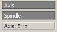
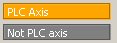
Axis type: Axis/Spindle
NC->PLC
DBax.DBX60.0

DBax = DB[30 + Axis Number]
Example: DB31 = Axis 1
Axis type:
0 = Axis
1 = Spindle
In case of a read error for axis data, 'Axis: error' is displayed here
Axis override:
PLC->NC
DBax.DBB0
DBax.DBB19

DBax = DB[30 + Axis Number]
Example: DB31 = Axis 1
Note: the displayed value is based on 'standard' settings for Gray code override

For axes, the override value is set from PLC to NC in DBax.DBB0.
For Spindles ('Axis type' (DBax.DBX60.0) = 1), spindle override is set from PLC to NC from DBax.DBB19

Channel-specific feedrate and rapid traverse [Not implemented in Monitor5]
For feedrate and rapid traverse override, dedicated enable signals and correction/offset factors are available in the NC/PLC interface:
DB21, ... DBX6.7 (feedrate override active)
DB21, ... DBB4 (feedrate override)
DB21, ... DBX6.6 (rapid traverse override active)
DB21, ... DBB5 (rapid traverse override)
The override factors can be specified from the PLC either in the binary or gray-coded format.
The format is communicated to the NC via the following machine data:
MD12020 $MN_OVR_FEED_IS_GRAY_CODE (path feedrate override switch gray-coded)
MD12040 $MN_OVR_RAPID_IS_GRAY_CODE (rapid traverse override switch gray-coded)

Axis-specific feedrate override
An enable signal and a byte for the feedrate override factor are in the NC/PLC interface for each positioning axis.
DB31, ... DBX1.7 (override effective)
DB31, ... DBB0 (feedrate override)
The override factor can be specified from the PLC either in the binary or gray-coded format.
The format is communicated to the NC via the following machine data:
MD12000 $MN_OVR_AX_IS_GRAY_CODE (axis feedrate override switch gray-coded)
The following permanent assignment applies to binary code: DBB0 = 0 => 0% ... DBB0 = 200 => 200%
With Gray coding, the override factors corresponding to the switch position must be entered in the machine data MD12010 $MN_OVR_ FACTOR_AX_ SPEED [n]

Spindle override
One enable signal and one byte for the spindle override factor are available in the NC/PLC interface for each spindle.
DB31, ... DBX1.7 (override effective)
DB31, ... DBB19 (spindle override)
The override factor can be specified from the PLC either in the binary or gray-coded format.
The format is communicated to the NC via the machine data MD12060 $MN_OVR_SPIND_IS_GRAY_CODE (spindle override switch gray-coded)
The following permanent assignment applies to binary code: DBB19 = 0 => 0% ... DBB0 = 200 => 200%
With Gray coding, the override factors corresponding to the switch position must be entered in the machine data MD12070 $MN_OVR_FACTOR_SPIND_SPEED [n]
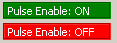
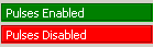
Pulse Enable:
PLC->NC
DBax.DBX21.7

DBax = DB[30 + Axis Number]
Example: DB31 = Axis 1
Pulse enable:
1 = ON: The pulses are enabled for the drive. The pulse enable is only performed in the drive when the drive signals readiness: DBax.DBX93.5 == 1 (feedback: Drive ready)
0 = OFF: The pulses are disabled for the drive.
If the pulse enable is removed during motion (e.g. emergency stop), the axis/spindle is no longer braked under control. The axis coasts to standstill.

Corresponding to: DBax.DBX93.5 (feedback: Drive ready); DBax.DBX93.7 (feedback: Pulses are enabled)
Controller Enable:
PLC->NC
DBax.DBX2.1

DBax = DB[30 + Axis Number]
Example: DB31 = Axis 1
Controller enable:
1 = ON: Controller is enabled.
The position control loop is closed and the axis/spindle is in closed-loop control.
Feedback: DBax.DBX61.5 = 1 (position controller active)
If the axis/spindle was referenced before resetting the interface signal, the axis/spindle does not have to be re-referenced after the interface signal is set again. Supplementary condition: The limit frequency of the active measuring system must not be exceeded in the meantime.
Note
If the axis/spindle was moved from its position during the time in which the controller enable was not set, the behavior when the controller enable is set depends on the interface signal "follow-up mode":
- DBax.DBX1.4 == 1 (follow-up mode): The position control is implemented on the current position
- DBax.DBX1.4 == 0 (no follow-up mode): The position control is made on the last position before the reset the controller enable


0 = OFF: Controller is not enabled.

The behavior when the "controller enable" is removed depends on whether the axis/spindle is stationary or traversing at this time:
- Axis/spindle stationary:
- The position control loop of the axis is opened.
- For DBax.DBX1.4 == 1 (follow-up mode) ⇒ position setpoint = actual position value
- The controller enable on the drive is reset
- The following interface signals are reset: DBax.DBX61.5 = 0 (position controller active); DBax.DBX61.6 = 0 (speed controller active); DBax.DBX61.7 = 0 (current controller active)
- Axis/spindle traverses
- The axis is stopped with rapid stop.
- Alarm 21612 "Controller enable VDI signal reset during motion".
- The position control loop of the axis/spindle is opened.
- Independent of the interface signal DBax.DBX1.4 (follow-up mode), the position setpoint is corrected at the end of the braking operation (position setpoint = actual position value) and the feedback signal DBax.DBX61.3 = 1 (follow-up mode) is set.
- The following interface signals are reset: DBax.DBX61.5 (position controller active); DBax.DBX61.6 (speed controller active); DBax.DBX61.7 (current controller active)
Feed Stop:
PLC->NC
DBax.DBX4.3

DBax = DB[30 + Axis Number]
Example: DB31 = Axis 1
Feedrate/spindle stop, axis-specific
0 = OFF: Feedrate/spindle stop is not active.
1 = ON: Feedrate/spindle stop is active.

Axis
- If the interface signal is set while traversing the axis, then the axis is braked down to standstill along its braking characteristic. If the axis is in an interpolatory relationship with other axes, these are also braked.
- After the interface signal has been reset, traversing motion that was stopped is continued.
- The position control is retained and the following error is eliminated.
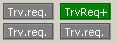
- If the interface signal is set, and a request is issued to traverse, then the axis is not traversed. However, the traverse request is kept. When the interface signal is reset, the traverse request is immediately executed, i.e. the axis is traversed.
- The interface signal is active in all modes.
Spindle
- If the interface signal is set while traversing the spindle, then the spindle is braked down to standstill along its braking characteristic. If the spindle is in an interpolatory relationship with other spindles, these are also braked.
- After the interface signal has been reset, traversing motion that was stopped is continued.
- During positioning, the position control is retained and the following error is eliminated.
- If the interface signal is set, and a request is issued to move during positioning operation, then the spindle is not moved. However, the traverse request is kept. When the interface signal is reset, the traverse request is immediately executed, i.e. the spindle is moved.
- The interface signal is active in all modes.
- The interface signal is not active during tapping (G331, G332).

Note:
In usual mode, the 'Feedrate/spindle stop' signal is generated by FC10 (standard bloc from Siemens ToolBox Library) in the PLC program.
Encoder 1 active:
Encoder 2 active:

PLC->NC
DBax.DBX1.5
DBax.DBX1.6


DBax = DB[30 + Axis Number]
Example: DB31 = Axis 1
Select active encoder...

Case 1: DBX1.5=0 DBX1.6 = 0:
Position measuring systems 1 and 2 are inactive ("parking" of the machine axis):
- There is no actual value acquisition.
- The monitoring of the position measuring system has been deactivated.
- The following interface signals are reset:
– DB31, ... DBX60.4 / 5 == 0 (referenced/synchronized, encoder 1/2)
– DB31, ... DBX61.5 (position controller active)
– DB31, ... DBX61.6 (speed controller active)
– DB31, ... DBX61.7 (current controller active)


Case 2: DBX1.5=1 DBX1.6 = 0:
Position measuring system 1 is active:
- Position control of the machine axis via position measuring system 1.
- Monitoring functions (measuring system, standstill, clamping monitoring, contour deviation, etc.) of the machine axis via position measuring system 1.
- If position measuring system 2 exists (MD30200 $MA_NUM_ENCS == 2), its actual position value is acquired, but not monitored by any of these functions.


Case 3: DBX1.5=0 DBX1.6 = 1:
Position measuring system 2 is active:
- Position control of the machine axis via position measuring system 2.
- Monitoring functions (measuring system, standstill, clamping monitoring, contour deviation, etc.) of the machine axis via position measuring system 2.
- If position measuring system 1 exists (MD30200 $MA_NUM_ENCS == 2), its actual position value is acquired, but not monitored by any of these functions.


Case 4: DBX1.5=1 DBX1.6 = 1:
- Position control of the machine axis via position measuring system 1.
- If position measuring system 2 is available (MD30200 $MA_NUM_ENCS == 2), its actual position value is also acquired.


Notes
- If the interface signal of the active position measuring system is reset for a traversing axis, the axis is stopped with a ramp stop without the controller enable being cancelled internally.
- If a speed-controlled spindle does not have a position measuring system, the "Controller enable" interface signal must be set: DB31, ... DBX2.1 == 1 (controller enable)
- After deactivation of the "parking" state, incremental position measuring systems have to be referenced to achieve the "referenced" encoder status.
- If the "parking" state is active, the following interface signal is ignored at NC start for this axis:
DB31, ... DBX60.4 / 5 (referenced/synchronized 1/ 2).
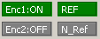
Encoder 1 referenced:
Encoder 2 referenced:

PLC->NC
DBax.DBX60.4
DBax.DBX60.5


DBax = DB[30 + Axis Number]
Example: DB31 = Axis 1
Encoder Referenced...

Encoder 1: DBX60.4:
REF: Signal state 1: Position measuring system 1 of the machine axis is referenced/synchronized.
N_Ref: Signal state 0: Position measuring system 1 of the machine axis is not referenced/synchronized.
Encoder 2: DBX60.5:
REF: Signal state 1: Position measuring system 2 of the machine axis is referenced/synchronized.
N_Ref: Signal state 0: Position measuring system 2 of the machine axis is not referenced/synchronized.
Traversing Key Disable:
PLC->NC
DBax.DBX4.4

DBax = DB[30 + Axis Number]
Example: DB31 = Axis 1
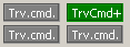
Traversing Keys Disable:
1 = ON: The "Plus" and "Minus" traversing keys are locked.
0 = OFF: The "Plus" and "Minus" traversing keys are enabled.

Corresponding to: DBax.DBX4.6 / DBax.DBX4.7 (traversing keys "Plus" / "Minus")
Delete Distance to Go:
PLC->NC
DBax.DBX2.2

DBax = DB[30 + Axis Number]
Example: DB31 = Axis 1
Delete Distance to Go: [Del DTG]
Edge change 0->1: Axis: "Delete-distance-to-go" is requested. Spindle: Reset is requested
Edge Change 1->0: No effect.

Axis: Delete distance-to-go
- AUTOMATIC and MDI modes
The interface signal is only active if the axis is traversed as positioning axis. A positioning axis is decelerated to standstill along its brake characteristic. The DistanceToGo of the axis is deleted.
- JOG mode
The axis is braked down to standstill alone its deceleration characteristic and then a possible delete distance to go is a deleted.

Spindle: reset
- Control mode:
--> The spindle is stopped
--> The NC program is again executed
--> The spindle continues to rotate with the next M and S value programmed in the NC program.
- Oscillation mode:
--> Oscillation is interrupted
--> The axes continue to traverse
--> The NC program continues with the actual gear stage
--> The spindle continues to rotate with the next M and S value programmed in the NC program. The speed obtained from these values (actual S value and the last active gear stage) could be too high. In this case, the interface signal is set. DBax.DBX83.1
- Positioning mode: The spindle is stopped
- Axis mode: The spindle is stopped

Note:
The response for a spindle reset is independent of the setting in machine data: MD35040 $MA_SPIND_ACTIVE_AFTER_RESET

Corresponding to:
DBch.DBX6.2 (delete distance-to-go)
DBax.DBX83.1 (programmed speed too high)
MD35040 $MA_SPIND_ACTIVE_AFTER_RESET (own spindle reset)
Hardware Limit Switches:
PLC->NC
Limit -: DBax.DBX12.0
Limit +: DBax.DBX12.1


DBax = DB[30 + Axis Number]
Example: DB31 = Axis 1
Hardware Limit Switch [Plus or Minus]:
1 = ON: The hardware limit switch ("Plus" or "Minus") was activated.
Alarm 21614 "Hardware limit switch -" is displayed, and the axis is stopped.
resp.
Alarm 21614 "Hardware limit switch +" is displayed, and the axis is stopped.

0 = OFF: The hardware limit switch ("Plus" or "Minus") was not activated.

Corresponding to: MD36600 $MA_BRAKE_MODE_CHOICE (deceleration behavior when the hardware limit switch responds)


Axis group 2:
Axial Alarm
NC -> PLC
DBax.DBX61.1

DBax = DB[30 + Axis Number]
Example: DB31 = Axis 1
1 = ON: An axis-specific alarm is output. The axis is braked down to standstill along its deceleration characteristic. Status of the axis is transitioned into "Single axis alarm is active".
0 = OFF: No axis-specific alarm.
Axis Ready
NC -> PLC
DBax.DBX61.2

DBax = DB[30 + Axis Number]
Example: DB31 = Axis 1
1 = ON: The axis is ready.
0 = OFF: The axis is not ready.

The signal is processed on the NCU to which the drive of the axis connected. The axis is not ready, if, on this NCU an alarm with system response "NC ..." or "Mode group..." or "Channel not ready" is displayed, which involves this specific axis.
Follow Up
NC -> PLC
DBax.DBX61.3

DBax = DB[30 + Axis Number]
Example: DB31 = Axis 1
1 = ON: The follow-up mode for the axis/spindle is active.
Possible causes:
- The controller enable for the drive has been withdrawn.
--> DBax.DBX2.1 == 0 (controller enable)
–-> in the control for faults; see under "Additional reference"
- Follow-up mode was selected:
–-> DBax.DBX1.4 == 1 (follow-up mode).
–-> in the control, e.g. when withdrawing the controller enable for a traversing axis
During the follow-up mode: position setpoint = actual position value

Note
The standstill and clamping monitoring are not active.

0 = OFF: The follow-up mode for the axis/spindle is not active. The standstill and clamping monitoring are active.

Note
In the "Hold" state, the "Follow-up mode active" signal is not set.
Position Control ON/OFF
NC -> PLC
DBax.DBX61.5

DBax = DB[30 + Axis Number]
Example: DB31 = Axis 1
1 = ON: The position controller is active, i.e. the position control loop of the axis/spindle is closed.
0 = OFF: The position controller is not active, i.e. the position control loop of the axis/spindle is not closed.
The signal is reset if the controller enable (DBax.DBX2.1 == 0) is reset by the PLC user program, or as a result of an internal fault.

Additional information
Spindle without position control
For a spindle without position control, the signal is always 0.
Spindle with position control
For spindles with the option of position control, after activating the position control, e.g.using SPCON or M70, then the signal is handled the same as for a position-controlled axis.
Vertical axis
For a vertical axis, the holding brake should be activated as soon as the position control is no longer active (DB31, ... DBX61.5 == 0).
Simulation axis
The output of the signal can also be parameterized for a simulation axis: MD30350 $MA_SIMU_AX_VDI_OUTPUT = 1
Speed Control ON/OFF
NC -> PLC
DBax.DBX61.6

DBax = DB[30 + Axis Number]
Example: DB31 = Axis 1
1 = ON: The speed controller is active, i.e. the speed control loop of the axis/spindle is closed.
0 = OFF: The speed controller is not active, i.e. the speed control loop of the axis is not closed. The speed controller output is cleared.

Additional information
Spindle without position control
If the spindle is not under position control, the signal can be used as a feedback signal for signal DBax.DBX2.1 (controller enable).
Simulation axis
The output of the signal can also be parameterized for a simulation axis: MD30350 $MA_SIMU_AX_VDI_OUTPUT = 1
Current Control ON/OFF
NC -> PLC
DBax.DBX61.7

DBax = DB[30 + Axis Number]
Example: DB31 = Axis 1
1 = ON: The current controller is active, i.e. the current control loop of the axis/spindle is closed.
0 = OFF: The current controller is not active, i.e. the current control loop of the axis is not closed. The current controller output, including the injection variables on the control voltage, is cleared.
Axis/spindle disable
PLC -> NC
DBax.DBX1.3

DBax = DB[30 + Axis Number]
Example: DB31 = Axis 1
1 = ON: Axis/spindle disable is requested.
0 = OFF: There is no request for "axis / spindle disable".

Axis:
- Effects with stationary axis:
--> No setpoints are output to the position controller, i.e. the axis traversing movement is disabled. The axis is in closed-loop position control and any remaining following error is compensated.
--> If the axis is traversed via an NC program or manually, the set position and set velocity are displayed as the actual position and actual velocity on the user interface. With channel reset or end of program (M30/M2), the display of the actual value is set to the actual value of the machine axis.
--> The travel commands are output to the NC/PLC interface.
- Effects with traversing axis:
--> The axis is stopped in compliance with the currently active braking characteristic and an alarm is displayed. Subsequently, the travel movements of the axis are disabled. Position control remains active and holds the axis in the current position.
Spindle:
- Effects with open-loop control mode and stationary spindle:
--> No setpoints are output to the speed controller, i.e. the spindle traversing movement is disabled.
--> If the spindle is traversed via an NC program or manually, the speed setpoint is displayed on the user interface as the speed actual value.
- Effects with open-loop control mode and rotating spindle:
--> Speed setpoint zero is immediately output to the speed controller.
--> The spindle is stopped in compliance with the currently active braking characteristic and an alarm is displayed. Subsequently, the travel movements of the spindle are disabled. Position control remains active and holds the axis in the current position.
- Effects with positioning mode: See Stationary axis / Traversing axis
Axis/spindle disable is active
NC -> PLC
DBax.DBX63.3

DBax = DB[30 + Axis Number]
Example: DB31 = Axis 1
1 = ON: Axis/spindle disable is active.
0 = OFF: Axis/spindle disable is not active.

PLC-controlled axis
NC -> PLC
DBax.DBX63.1

DBax = DB[30 + Axis Number]
Example: DB31 = Axis 1
1 = ON: Axis control is transferred to the PLC.
0 = OFF: The axis is controlled by the NC.

Corresponds with DBax.DBX28.7 (request, PLC-controlled axis)
Active Handwheel
NC -> PLC
DBax.DBX64.0...64.2

DBax = DB[30 + Axis Number]
Example: DB31 = Axis 1
Number of active Handwheel

MD11324 = 0:
DBax.DBX64.2DBax.DBX64.1DBax.DBX64.0Handwheel
000NO Handwheel active
001Handwheel 1 active
010Handwheel 2 active
100Handwheel 3 active

MD11324 = 1:
DBax.DBX64.2DBax.DBX64.1DBax.DBX64.0Handwheel
000NO Handwheel active
001Handwheel 1 active
010Handwheel 2 active
011Handwheel 3 active
100Handwheel 4 active
101Handwheel 5 active
110Handwheel 6 active
Traversing request "Plus" / "Minus"
NC -> PLC
DBax.DBX64.4
DBax.DBX64.5


DBax = DB[30 + Axis Number]
Example: DB31 = Axis 1
1 = ON: There is a traversing request for the machine axis.
0 = OFF: There is no traversing request for the machine axis.

Traversing command "Plus" / "Minus"
NC -> PLC
DBax.DBX64.6
DBax.DBX64.7


DBax = DB[30 + Axis Number]
Example: DB31 = Axis 1
1 = ON: A travel command is pending for the machine axis
0 = OFF: No travel command is pending for the machine axis

The travel command is output depending on MD17900 $MN_VDI_FUNCTION_MASK, bit 0.


Axis Safety:
Safety Mode:
NC->PLC
DBax.DBX70.4
DBax.DBX70.5
Safety Mode for axis:
DBax.DBX70.4 = 1: NC Safety Integrated Active (Safety Integrated 'Classic')
DBax.DBX70.5 = 1: DRV Safety Integrated active with SIC/SCC (Safety Integrated 'Plus' with PLC S7-F Failsafe and Safety Integrated from Drives)

Note:
Monitor5, in version 20.xx.xx is monitoring only the Signal for Safety Integrated 'Classic'
SBH Request:
PLC->NC
DBax.DBX22.0
DBax.DBX22.1
SBH deselection
SBH - Sicherer Betriebshalt = SOS - Safe Operating Stop
SG - sichere geschwindigkeit = SLS - Safe Limited Speed


DBax.DBX22.0 = SBH/SG deselection
DBax.DBX22.1 = SBH deselection

Bit:SBH [SOS] SELECTEDSG [SLS] SELECTEDNO SBH or SG SelectedNO SBH or SG Selected
DBax.DBX22.00011
DBax.DBX22.10101
SOS Status:
NC->PLC
DBax.DBX108.0 SBH [Sichere Betriebs Halt = Safe Operating Stop / SOS] is Active
SG Request:
PLC->NC
DBax.DBX22.0
DBax.DBX22.1
SG deselection
SBH - Sicherer Betriebshalt = SOS - Safe Operating Stop
SG - Sichere Geschwindigkeit = SLS - Safe Limited Speed


DBax.DBX22.0 = SBH/SG deselection
DBax.DBX22.1 = SBH deselection

Bit:SBH [SOS] SELECTEDSG [SLS] SELECTEDNO SBH or SG SelectedNO SBH or SG Selected
DBax.DBX22.00011
DBax.DBX22.10101
SLS Status:
NC->PLC
DBax.DBX110.1 SG [Sichere Geschwindigkeit = SLS - Safe Limited Speed] is Active
SG Stage:
PLC->NC
DBax.DBX22.3
DBax.DBX22.4
SG Stage Request:
SG - Sichere Geschwindigkeit = SLS - Safe Limited Speed

Bit:SG Stage 1SG Stage 2SG Stage 3SG Stage 4
DBax.DBX22.30101
DBax.DBX22.40011
SG Stage:
NC->PLC
DBax.DBX110.3
DBax.DBX110.4
Actual SG Stage:
SG - Sichere Geschwindigkeit = SLS - Safe Limited Speed

Bit:SG Stage 1SG Stage 2SG Stage 3SG Stage 4
DBax.DBX110.30101
DBax.DBX110.40011
STOP A Request:
PLC->NC
DBax.DBX32.2 STOP A Requested

"Pulse cancellation" can be requested and executed using this SGE.
The safe functions currently active (SG/SBH/SN/SE) are not influenced by this SGE.
If one of the currently active limits is violated, an appropriate alarm is initiated. The associated shutdown response cannot be activated because the pulses have already been cancelled. As soon as the stop request is cancelled via the SGE "deselect ext. STOP A" any queued shutdown responses become active.
If a stop request is active, SGA "STOP A/B is active" is set in the same way as it would be for an internally triggered STOP A.

0 signal: "Pulse cancellation" is requested
1 signal: "Pulse cancellation" is not requested
STOP A Active:
NC->PLC
DBax.DBX111.4 STOP A is Active
This signal indicates that STOP A/B is active.The signal must be used for the forced checking procedure for external STOPs.
0 signal: STOP A/B is not active
1 signal: STOP A/B is active
STOP C Request:
PLC->NC
DBax.DBX32.3 STOP C Requested

This SGE requests "braking with nset = 0" (braking along the OFF3 down ramp).
When this stopping type is initiated, the safe monitoring of the acceleration (SBR) is activated. In addition, the timer set using MD36952/p9552: $MA_SAFE_STOP_SWITCH_TIME_C / "SI Motion transition time STOP C to SBH" is started.
After this time has elapsed, the system automatically changes over to SBH.
If a stop request is active, SGA "STOP C is active" is set in the same way as it would be for an internally triggered STOP C.

0 signal: "Braking with nset = 0" is requested
1 signal: No request for "Braking with nset = 0"

Note
Stopping with an external STOP A (pulse cancellation) has a higher priority and can interrupt an external STOP C (braking along the OFF3 down ramp).
STOP C Active:
NC->PLC
DBax.DBX111.5 STOP C is Active
This signal indicates that STOP C is active.The signal must be used for the forced checking procedure for external STOPs.
0 signal: STOP C is not active
1 signal: STOP C is active
STOP D Request:
PLC->NC
DBax.DBX32.4 STOP D Requested

"Braking along a path" can be requested using this SGE.
When ext. STOP D is triggered, the timer set using MD36953/p9553 $MA_SAFE_STOP_SWITCH_TIME_D / "SI Motion transition time STOP D to SBH" is started.
After this time has elapsed, the system automatically changes over to SBH.
If a stop request is active, SGA "STOP D is active" is set in the same way as it would be for an internally triggered STOP D.

0 signal: "Braking along a path" is requested
1 signal: No request for "Braking along a path"

Note
Stopping with an external STOP A (pulse cancellation) and/or external STOP C (braking along the OFF3 down ramp) has a higher priority and can interrupt an external STOP D (braking along a path).
STOP D Active:
NC->PLC
DBax.DBX111.6 STOP D is Active
This signal indicates that STOP D is active.The signal must be used for the forced checking procedure for external STOPs.
0 signal: STOP D is not active
1 signal: STOP D is active
STOP E Request:
PLC->NC
DBax.DBX32.5 STOP E Requested
This SGE can be used to request a stop via the function "extended stopping and retraction" (ESR).
When an external STOP E is initiated the timer set using MD36954: $MA_SAFE_STOP_SWITCH_TIME_E / p9554: Timer set for "SI Motion transition time STOP E to SBH" is started.
After this time has elapsed, the system automatically changes over to SBH.
If a stop request is active, SGA "STOP E is active" is set in the same way as it would be for an internally triggered STOP E.

0 signal: "Stop/retraction" is requested
1 signal: "Stop/retract" is not requested

Note
Stopping with an external STOP A (pulse cancellation) and/or external STOP C (braking along the OFF3 down ramp) and/or ext. STOP D (braking along a path) has/have a higher priority and can interrupt an external STOP E.

STOP E only produces a different response than STOP D if the user has configured the ESR function - extended stop and retract - and initiation of the ESR is programmed depending on $VA_STOPSI or $A_STOPESI. If no ESR is active, the STOP E behaves like a STOP D. However, if the ESR was incorrectly configured, there is a delay up to the time $MC_ESR_DELAY_TIME1 and $MC_ESR_DELAY_TIME2 compared to STOP D until the braking operation is initiated.
After these times have expired, braking is initiated at the current limit.
STOP E Active:
NC->PLC
DBax.DBX111.7 STOP E is Active
This signal indicates that STOP E is active.The signal must be used for the forced checking procedure for external STOPs.
0 signal: STOP E is not active
1 signal: STOP E is active
Pulses are Enabled
NC->PLC
DBax.DBX108.2 Pulses are Enabled [from Safety]